Avoidance of excessive pressure rises of trapped thermal oil or water in pipelines

If thermal oil or water is trapped in pipe ends or pipelines – e.g. during maintenance work – and heated therein, it expands greatly and leads to a massive pressure increase in the affected area. The heating of the enclosed liquid can take place due to various external influences, e.g. heat conduction of hot medium from plant areas nearby, solar radiation or heating due to an external fire.
The resulting increase in pressure can cause damage to fittings as well as pipelines and, in the worst case, lead to a leakage of thermal oil or hot water.
The effect of heating by thermal conduction occurs mainly when the associated pipe section is insulated and thus no cooling by thermal conduction and/or heat radiation to the environment can take place.
Theory
In order to find a measure for a pressure increase, we now take a closer look at a filled pipeline. The calculation below describes this pressure rise for the thermal oil type Mobiltherm 603 as an example:

Conclusion: With a completely filled pipeline, there is a pressure increase of approx. 6 bar per 1 K temperature increase for Mobiltherm 603.
In general, the value for the coefficient of volume expansion for thermal oils varies between the values 0.00065 and 0.00095 1/K. Thus, depending on the type of thermal oil, the pressure increase can be between 6 and 10 bar per Kelvin temperature increase. For water at 90°C, the coefficient of volume expansion is 0.000696 1/K and is thus in the same magnitude.
Effects
Depending on the design of the affected area, the effects are different. If the closing pressure of the valve is lower than the failure pressure of the seal and the pressure rise is located before the seat of the stop valve, the poppet is pressed into the actuator. As a result, only an undefined opening of the valve occurs and medium as well as pressure can be exchanged between the two areas.
The situation is different if the pressure increase occurs behind the seat of a stop valve or the closing pressure of the valve is greater than the failure pressure of the seal. In this case, the pressure cannot escape, so massive damage can occur to the valve or another component in the section with the high pressure.
Due to the high pressure behind the valve seat, the sealing surface, which separates the medium from the actuator area, is pressed against the housing. In addition, a change can be seen on the bellows. Elastic as well as plastic deformations occur at the valve. After failure of the graphite seal, thermal oil escapes from the separated area, causing the pressure there to decrease and the elastic deformation to return. The plastic deformation at the valve remains and opens it partially. This creates a connection from the main system to the environment, which can result in a major leakage.

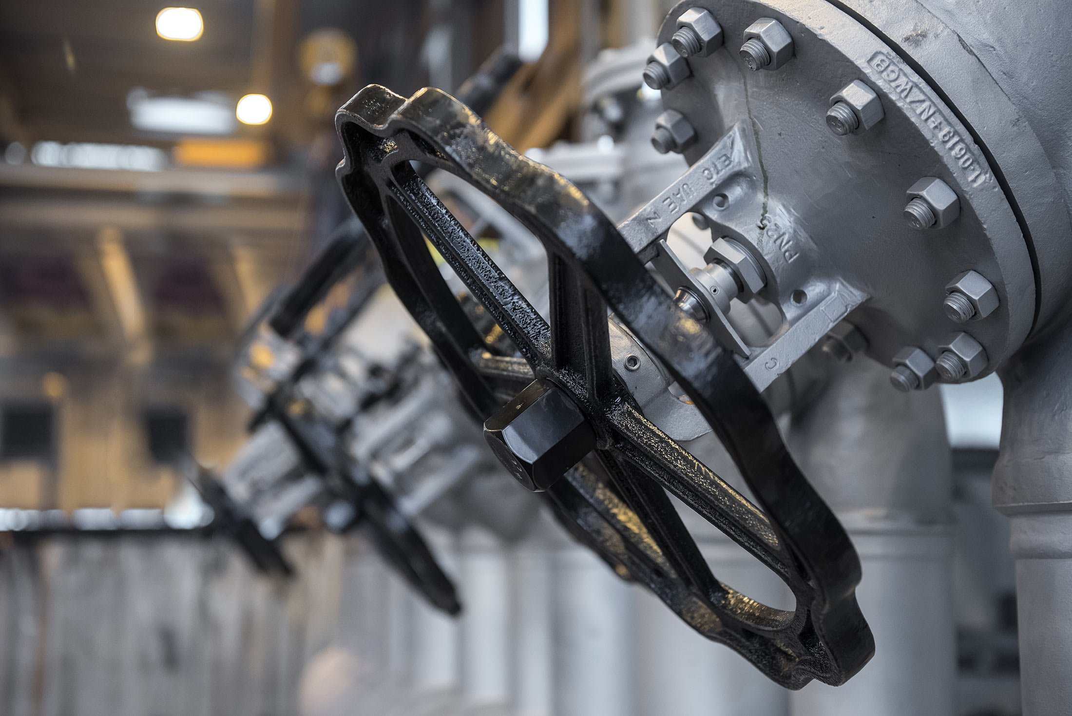
Damaged angle seat valve

Intact angle seat valve
Recommendations for action
The following is required for safe operation of the systems:
- In case of a valve shuts off a closed pipeline end (welded cap or blind flange), it must be open during operation. It is recommended to secure these valves in their correct position, e.g. with a plastic safety device.
- In case of the valve cannot be opened at a pipeline end, the pipeline end after the valve must not be insulated and it must not be completely filled with liquid. There must be a gas cushion.
- In case of two valves are installed one behind the other in a pipe section and both must be closed for safety reasons (“double block”), we recommend installing a test and drain valve in the intermediate space. This allows to empty the space in between, fill the pipe section with air, and prevent excessive pressure buildup by the compressible medium.
- In case of two valves are installed one after the other in drain pipes, care must be taken to ensure the correct closing sequence.
The actions above are of particular importance when valves and nozzles are insulated.
Service interventions (e.g. maintenance) or temporarily closed quick-closing flaps due to safety circuits can lead to temporary trapping of thermal oil. Here, care must be taken to ensure that these conditions are kept as short as possible in order to avoid pressure increases or vacuum. In addition, pressure monitoring or other actions are recommended.
Example: Reserve connection with welding pipe cap or blind flange
This is implemented, for example, at unused connections of manifolds or to connect temporarily used equipment to the overall system.
As the welded pipe cap and the flange-soft seal-blind flange connection are considered to be technically tight, we recommend that the valve is always left open during normal operation. The test and drain valve must be closed during operation.

Reserve connection with weld-on cap

Reserve connection with blind flange
Example: Two valves one after the other in the piping system
For safety reasons, two valves are installed in series in the piping system, called “double block”.
This application as an example for the connection of the entire system to an expansion tank. In the event that the expansion tank has to be disconnected from the system, both shut-off valves must always be closed. This is necessary because redundancy and the associated safety have the highest priority.
To avoid trapping thermal oil between the two shut-off devices, a test and drain valve must be installed between them. This allows to empty the space in between, fill the pipe section with air, and prevent excessive pressure buildup by the compressible medium.

Connection to the expansion tank
Example: Two valves one after the other with open line end
This case occurs, for example, at tank emptying. To prevent trapping of thermal oil, attention must be paid to the sequence when closing the valves: The shut-off valve that is closer to the medium must be closed first. Only if no more thermal oil flows out of the open end of the line may the second, outer valve be closed.