News
 Emission reduction at thermal oil plants7. April 2025 - 9:00
 EGGER Unterradlberg – From gas-fired heaters to biomass21. November 2024 - 10:44
 Olaf Bernhard on heating/cooling systems and projects in Turkey7. November 2024 - 15:02
 Thomas Krauss on manufacturing at NESS7. November 2024 - 14:58
Galerie
-
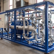
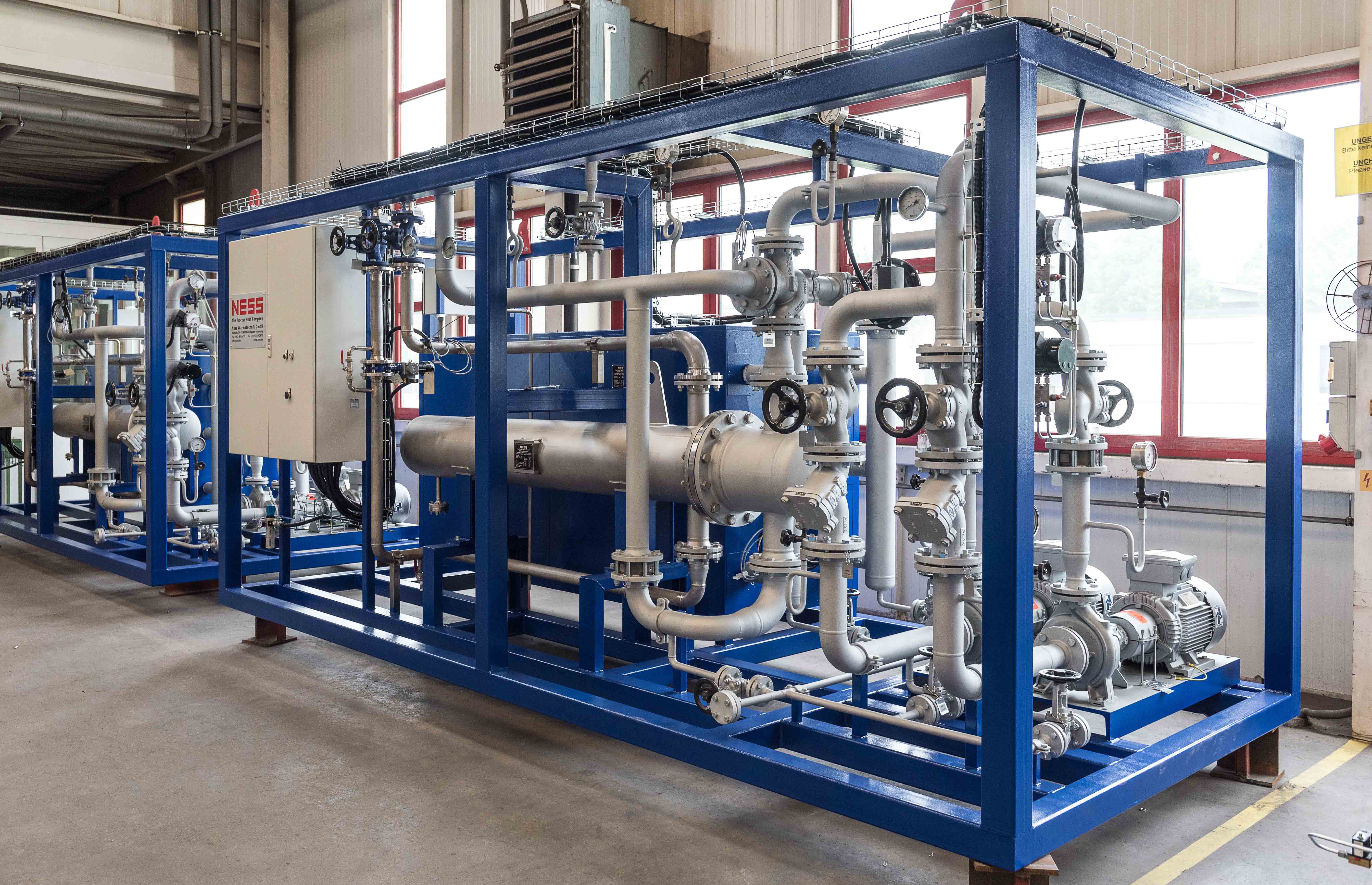
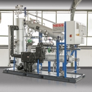
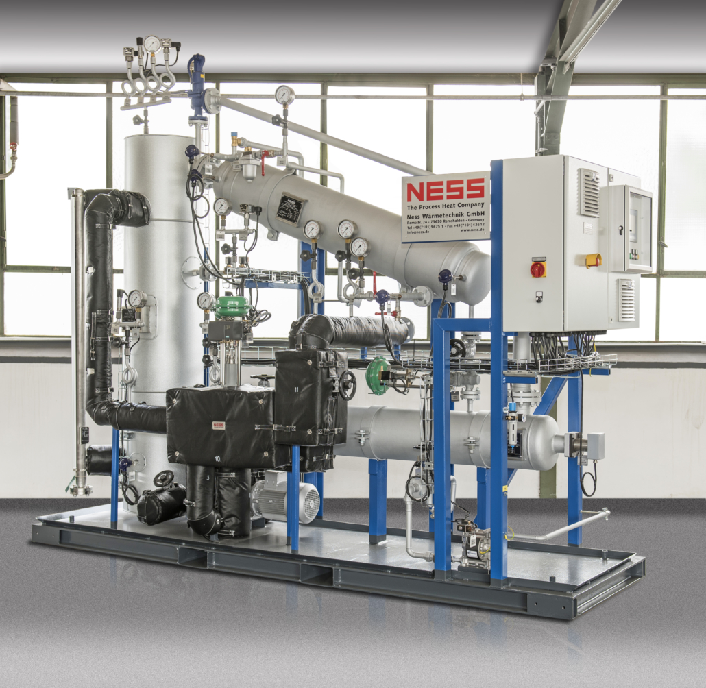
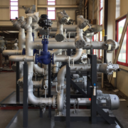
- Installations de chauffage-refroidissement
-
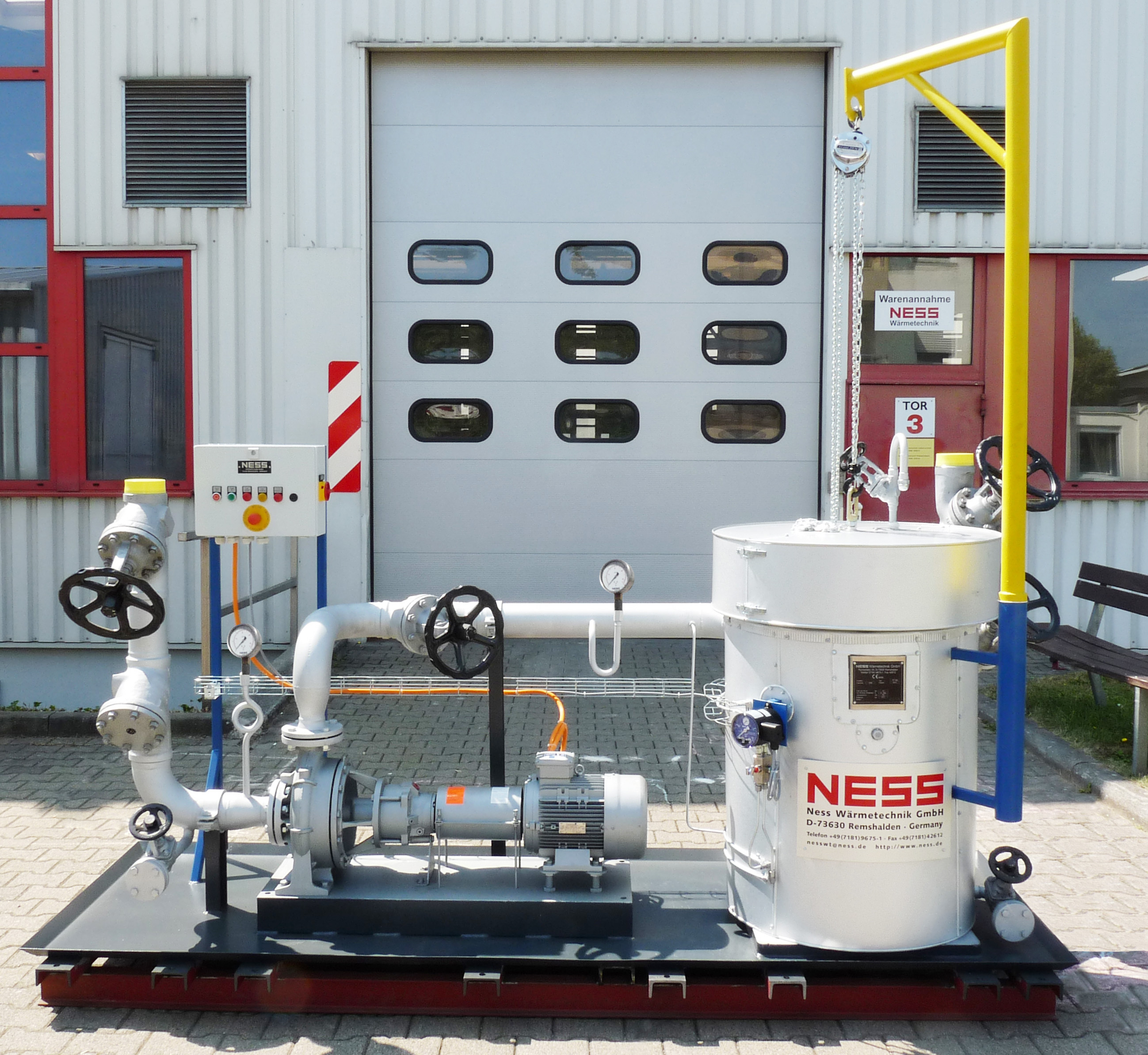
- water-cooled aktiv-system (NALD250)
-
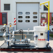
- NESS Fine filter station (FF500)
-
- Installations de chauffage-refroidissement
-
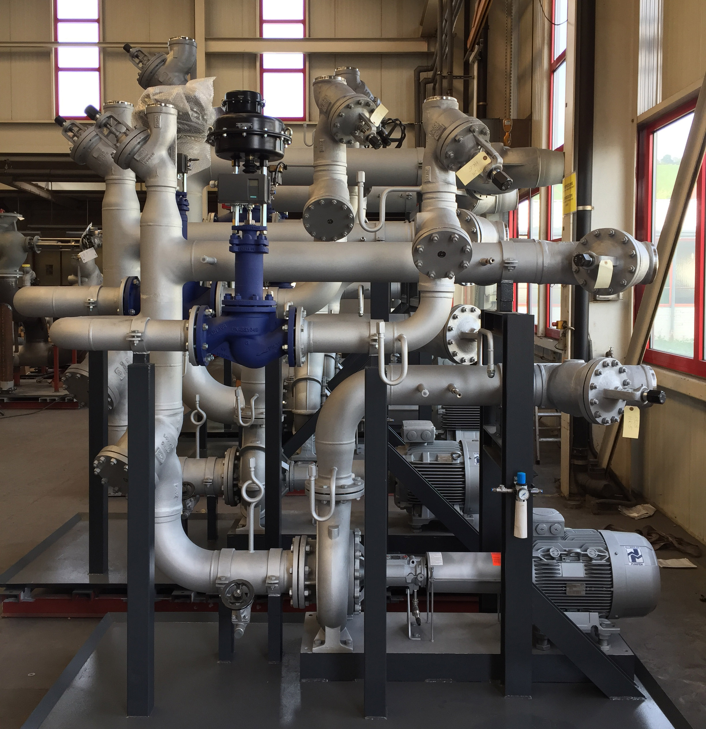
- Secondary circuits
-
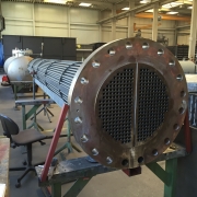
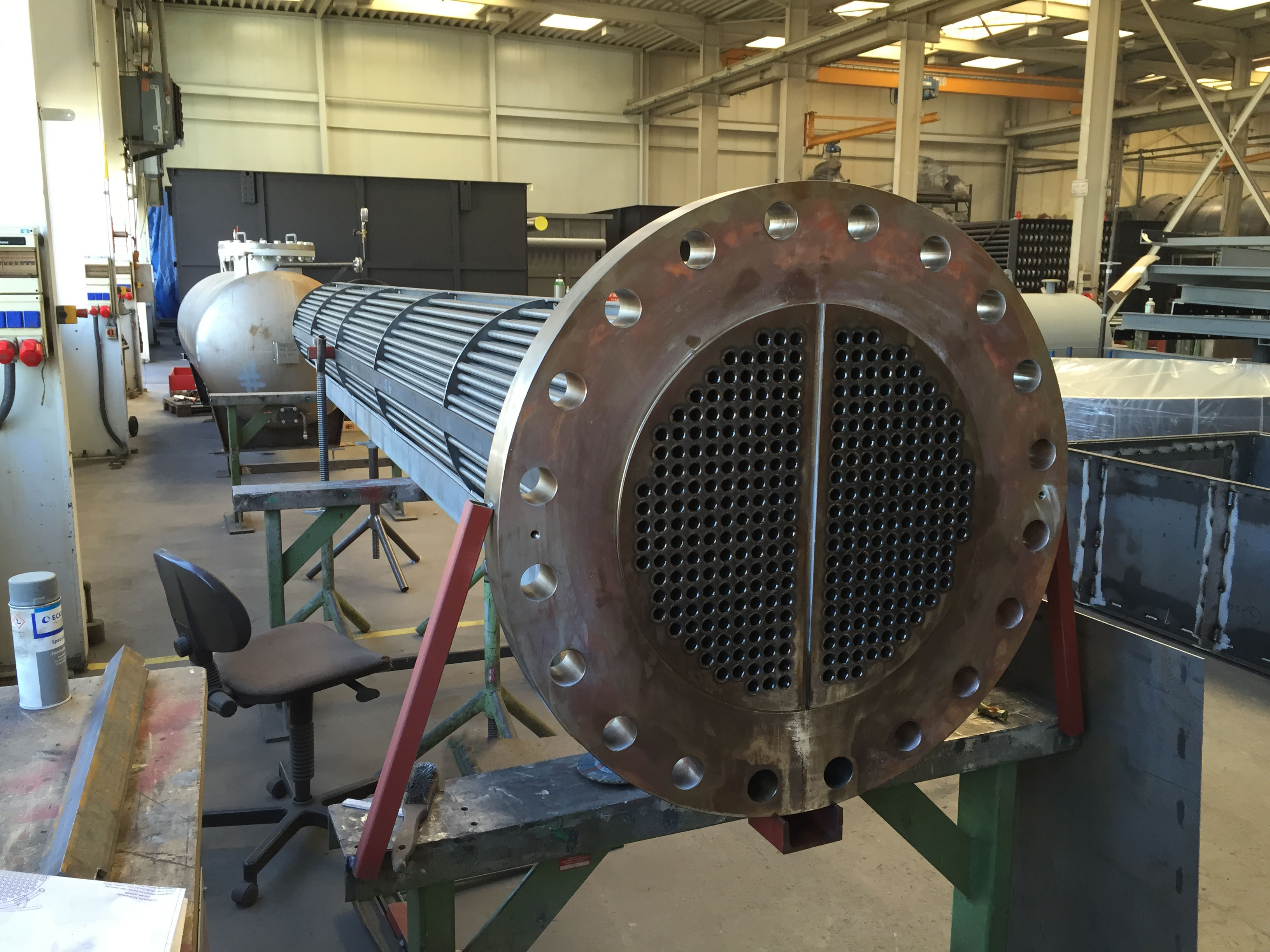
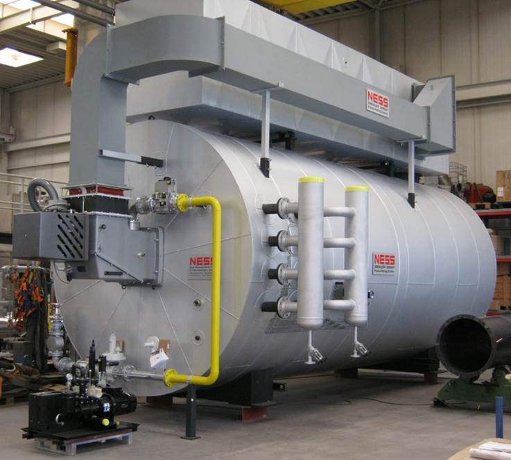
- Échangeur thermique